Technical Specifications
WXQ300 Series — Complete Technical Reference
Core Technical Parameters
| Parameter | Value / Description |
|---|---|
| Output Frequency | 0-600Hz |
| Overload Capacity | 150% rated current 1min, 180% rated current 3s |
| Modulation Type | Optimized space voltage vector (SVPWM) modulation |
| Control Mode | Sensorless vector control (with optimized low-frequency dead-zone compensation) |
| Frequency Resolution | Digital setting: 0.01Hz; Analog setting: Max frequency × 0.025% |
| Starting Frequency | 0.0-10.0Hz |
| Torque Boost | Auto torque boost, Manual torque boost 0.1%-30.0% |
| Built-in PID | Easy to constitute closed-loop control system |
| Multi-Speed Operation | Via built-in PLC or control terminal, multi-speed operation can be achieved |
| Running Command Channel | Control panel reference, Control terminal reference, 485 communication |
| Digital Input Channel | Forward/reverse instructions: 5 programmable digital inputs |
| Analog Input Channel | 1 channel analog signal input, 0-20mA, 0-10V |
| Analog Output Channel | 4-20mA or 0-10V selectable, can realize setting frequency output, etc. |
| Relay Output Channel | 2 channels of relay output signal |
| Protection Function | Over-current, Over-voltage, Under-voltage, Over-heat, Overload, Short-circuit |
| PV Power Tracking | CVT mode, MPPT mode |
Control Panel Specifications
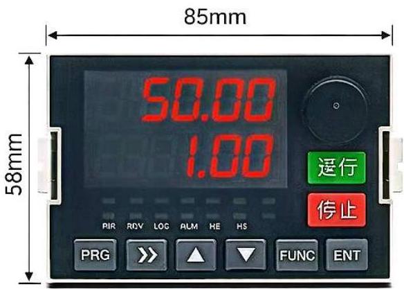
Standard Panel
- Panel Dimensions: 85mm × 58mm
- Display: Dual Line, Red Digit LED Display
- Keys: PRG, Arrows, FUNC, ENT
- Buttons: RUN & STOP
- Cutout Size: 99mm × 68mm
Enhanced Panel
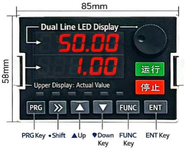
- Panel Dimensions: 85mm × 58mm
- Display: Dual Line LED Display (Upper: Set Value / Lower: Actual Value)
- Keys: PRG, Shift, Up, Down, FUNC, ENT
- Buttons: RUN & STOP
- Feature: Remote Mountable with Extension Cable
Main Circuit Terminals
| Terminal Label | Name | Description |
|---|---|---|
| R/L1, S/L2, T/L3 | Power Input Terminals | Connect to AC power source points |
| PP, PB | Brake Resistor Connection | Connect to the brake resistor |
| U, V, W | Inverter Output Terminals | Connect to three-phase motor |
| U, V (H2) | Inverter Output Terminals | Connect to single-phase motor |
| ⏚ Ground | Ground Terminal | Connect to power distribution box ground terminal or other regulated grounding points |
Control Terminal Function Description
| Category | Terminal | Name | Function Description |
|---|---|---|---|
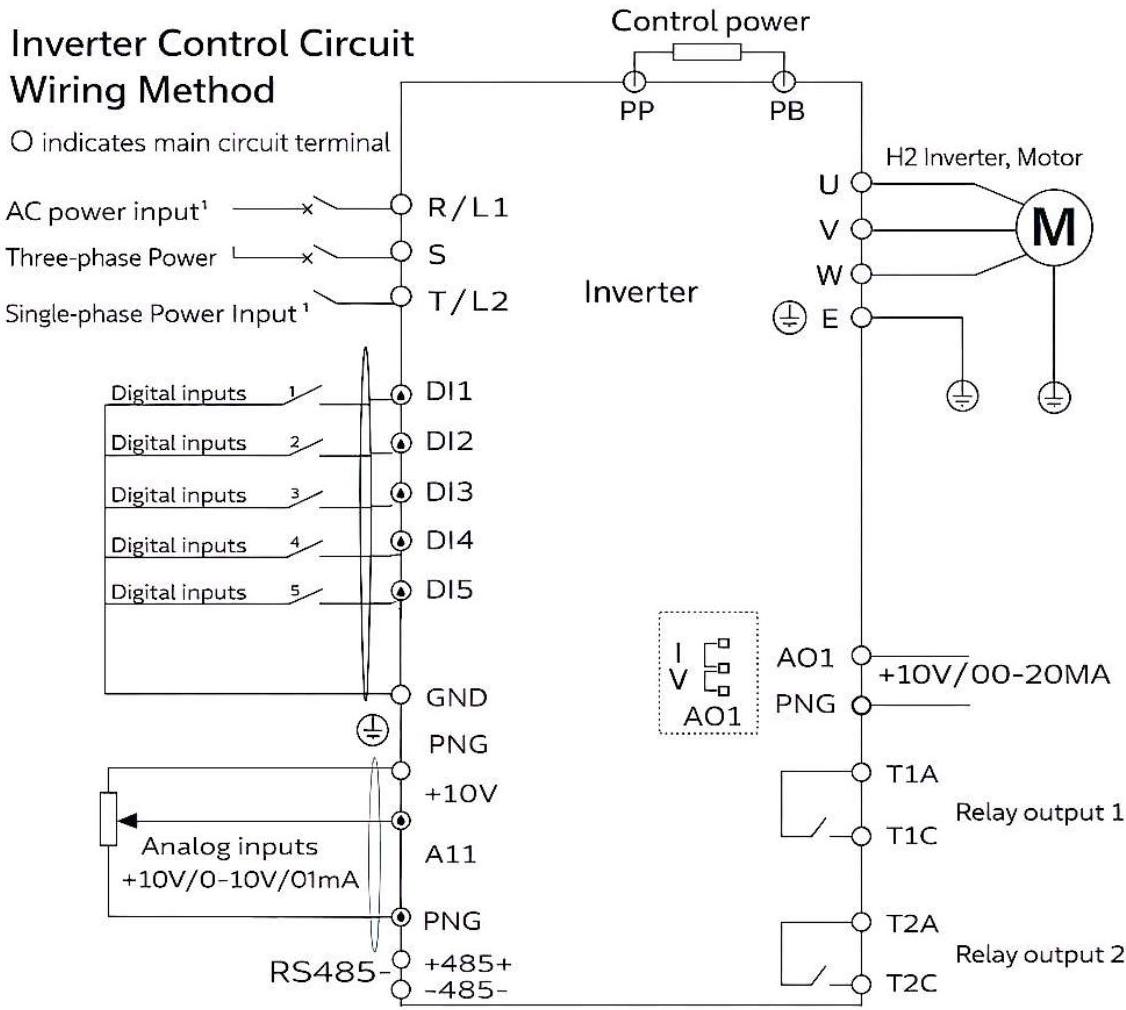
| Power | +10V-GND | External +10V | Provides +10V power supply, max output current 50mA. Used as external potentiometer power supply (1kΩ-5kΩ) |
| +24V-GND | External +24V | Provides +24V power supply, used for digital I/O and external sensor, max 200mA | |
| Analog Input | AI1-GND | Analog Input 1 | Input range: DC 0-10V / 0-20mA; Input resistance: 22kΩ (voltage), 500Ω (current) |
| DI1~DI5-GND | Digital Input 1-5 | 5 programmable digital input channels, voltage range: 5V-30V | |
| Analog Output | AO1-GND | Analog Output 1 | Output: 0-10V / 0-20mA |
| Relay Output | T1A-T1C | Relay 1 (NO) | Contact capacity: AC250V/3A, DC30V/1A |
| T2A-T2C | Relay 2 (NO) | Contact capacity: AC250V/3A, DC30V/1A |
6 Comprehensive Safety Protections

Over-Voltage Protection
Monitors DC bus voltage and shuts down when exceeding safe threshold

Under-Voltage Protection
Protects against power supply drop to prevent damage to components

Over-Current Protection
Limits output current to prevent IGBT damage during motor stall or overload
Over-Temperature Protection
Heat sink temperature monitoring with automatic frequency reduction

Phase Loss Protection
Detects input/output phase loss condition and triggers alarm
Short-Circuit Protection
Instant shutdown upon detecting output short-circuit to protect IGBT module
Electrical Installation Guide
⚠️ Signal Input Terminal Wiring Instructions
- Use shielded cables for all signal wiring to prevent electromagnetic interference
- Keep signal cable distance as short as possible
- Separate signal cables from power cables
- Under severe interference conditions, install filtering components
- Connect shield layer to ground terminal at inverter side only (single-point grounding)